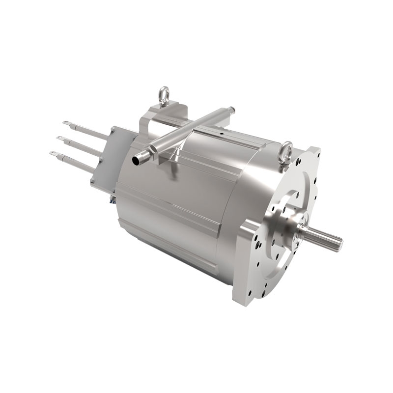
In the current production conditions, when using frequency converter to form an automatic control system for control, in many cases, it is necessary to use PLC and frequency converter to match, such as bearing cleaning, packaging paper printing, PCB production, etc.
PLC can provide on-off signals of various control signals and instructions through output point or communication. The following introduces the matters needing attention when the inverter and PLC cooperate.
1. Input of switch command signal
The input signal of frequency converter includes the switch type command signal to control the operation states such as operation / stop, forward / reverse rotation, segment speed and inching. Frequency converter usually uses relay contact or components (such as transistors) with relay contact switch characteristics to connect with PLC to obtain operation status instructions.
When using relay contacts, misoperation is often caused by poor contact; when connecting with transistors, the voltage and current capacity of transistors should be considered to ensure the reliability of the system.
When designing the input signal circuit of frequency converter, attention should be paid to that when the input signal circuit is not connected properly, it will also cause the malfunction of the frequency converter. For example, when the input signal circuit uses the inductive load such as relay, the surge current generated by the relay opening and closing may cause damage or failure of the internal components of the frequency converter, and then cause the frequency converter to malfunction. Therefore, this situation should be avoided as far as possible.
When the input switch signal enters the frequency converter, the crosstalk between the external power supply and the converter control power supply (DC24 V) sometimes occurs. The correct connection is to use PLC power supply to connect the collector of external transistor to PLC through diode.
2. Input of numerical signal
There are also some numerical command signals (such as frequency, voltage, etc.) in the inverter, which can be divided into analog input and analog output. The analog input is given from outside through the terminal, usually through the voltage signal of 0-10V / 5V or the current signal of 0 / 4-20mA. Because the interface circuit varies with the input signal, the output module of PLC must be selected according to the input impedance of frequency converter.
When the voltage signal range of frequency converter and PLC is different, such as the input signal of frequency converter is 0 ~ 10V, while the output voltage signal range of PLC is 0 ~ 5V; or when the output signal voltage range of PLC side is 0 ~ 10V and the input voltage signal range of inverter is 0 ~ 5V, due to the limitation of allowable voltage and current of frequency converter and transistor, parallel and series connection mode is needed The resistance is connected to limit the current or part of the voltage to ensure that the corresponding capacity of PLC and inverter is not exceeded when opening and closing. In addition, attention should be paid to separate the control circuit from the main circuit when connecting the wire. It is better to use shielded wire to ensure that the noise on one side of the main circuit will not be transmitted to the control circuit.
Note: the input impedance of PLC side should ensure that the voltage and current in the circuit do not exceed the allowable value of the circuit, so as to ensure the reliability of the system and reduce the error.
In addition, when using PLC for sequence control, due to the time required for data processing, the different order of programming and the different use of instructions, there will be a certain time delay in the operation of the system, so the above factors should be considered in more accurate control.
Because the inverter will produce strong electromagnetic interference in the operation, in order to ensure that PLC will not be fault because of the noise generated by the main circuit breaker and switching devices of the inverter.
Therefore, the following points should be paid attention to when the inverter is connected with PLC:
(1) PLC itself should be grounded according to the specified wiring standards and grounding conditions, and attention should be paid to avoid using common ground wire with frequency converter, and the two should be separated as far as possible during grounding.
(2) When the power supply condition is not good, noise filter, reactor and devices that can reduce noise should be connected to the power line of PLC power module and I / O module. In addition, if necessary, corresponding measures should be taken at the input side of frequency converter.
(3) When the frequency converter and PLC are installed in the same operation cabinet, the wires related to frequency converter and PLC shall be separated as far as possible.
(4) Through the use of shielded wire and twisted pair to improve the level of noise interference.

|
|

|
| The public, | Mobile station |
 0755-81719517
|
|
 0755-81719530 0755-81719530 |
 amb@ambition.com.cn amb@ambition.com.cn |
 Floor 1, 5 and 6, building 7, lijincheng science and technology industrial park, gongye dong road, longhua new district, shenzhen Floor 1, 5 and 6, building 7, lijincheng science and technology industrial park, gongye dong road, longhua new district, shenzhen |
|

 English
 中文
中文